Invention of the Mechanical Explosive Igniter

It’s been a while since my last post – other things have had my attention. A reader, John C, responded to a post I wrote last year with some thoughts and this encouraged me to look again at this fascinating and crucially important piece of (explosive) history.

This then is a follow up to this post   which I suggest you read through to refresh your memory. In it I explore some interesting technological developments regarding the development of explosive initiators in the early 1500s.  Why is this important?

    1. Until the early 1500s, explosives (gunpowder) could only be initiated by the physical application of fire. Gunpowder was initiated by applying a burning match to a small quantity of gunpowder which then ignited a larger charge, whether that be inside a gun or inside a larger container.
    2. Effectively this limited the use of explosives/gunpowder, because a prior step was needed to ignite a match and keep it burning until such time as it could be used.  This limited how explosive devices or firearms could be used, slowing the process or making it more obvious. So the technology development described below allows for speed of action, timeliness and concealment – all important characteristics of explosive devices.
    3. The invention of a mechanical igniter gave much more flexibility and did away with the need for a burning match. Devices could be placed, concealed and left. Firearms could be concealed.  Devices or firearms could also be initiated almost exactly when needed rather than after a delay.
    4. Mechanical igniters such as this enabled booby traps (Victim operated devices) (perhaps with a trip wire), enabled command operated explosive devices (via a pull string) and even enabled timed explosive devices (where a clock hand could pull a string). As far as firearms are concerned the jump from matchlock to wheel-lock is a very significant technological leap.

So in the history of firearms and in the linked history of explosives (as the site purports to be, in a sense)  these mechanical devices described in my earlier post are quite significant.

In the earlier post last year I included a copy of beautiful diagram of a mechanical igniter from a date of about 1505. Historically speaking this is technically a wheel lock but I think was invented before a similar device was fitted to a hand held firearm. It’s maybe the first wheel lock mechanism.  This device and one or two others were carefully drawn and included in the“Loffelholz Kodex”. At the time I hadn’t worked out how this igniter had functioned. I’ve now spent some time scratching my head and doing a little research and I think I may have an answer. But I’m only about 60% certain, so if you think I’m wrong, please correct me. I’m very open to alternative interpretations of this intriguing machine.  For ease of explanation I have included the diagram again here below but with some annotations.
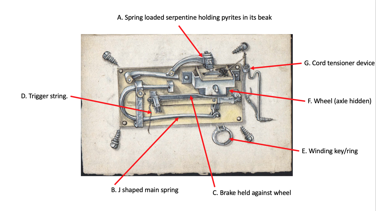
I originally thought the device had a coiled spring hidden behind the wheel (F) to cause it to turn, but I no longer think that is true. Importantly I don’t think coiled springs of the type I had envisioned had been invented at this time.  Rather, like the simpler device seen in the last post, there is a cord wrapped around the wheel’s axle. The horizontal J shaped main spring (B) has its longest arm, along the bottom and this is the spring which pulls the cord down, causing the wheel to spin. The wheel is prevented from turning by the Brake (C) in the middle to which a pull string is attached. Pulling that away from the wheel is like releasing a parking brake. In normal conditions this Brake (C) is held in place by the brass bar running in parallel to it acting as a spring.  The bit I’m slightly unsure of is the Cord tensioner (G). This holds the cord tight against the axle. You can see the finger holder that you pull when winding up the wheel(F) with the winding key (E).

So… let me describe the preparation and action…

1. The winding cord is tied to the end of the J shaped main spring and the other end to to the right hand contraption. The right hand contraption is tensioned using the finger guard to pull the cord.
2. The wheel is turned using the “ring key”. This causes the cord to wrap around the axle of the wheel. (Somehow!)
3. As this is done the J spring is flexed upwards, and held there by the cord.
4. The “brake” acting on the wheel prevents the tension of the cord to act on the wheel. .
5. After a few turns the brake is engaged, holding the wheel.
6. The tray is primed with gunpowder or tinder.

The action on firing is as follows:

1. At the chosen time the string is pulled.
2. This pulls the brake away from the wheel.
3. The J spring now acts pulling the cord down that is wrapped around the wheel’s axle.
4. The wheel rotates
5. The serpentine holds the pyrites against the rotating wheel
6. Sparks are generated and thrown into the gunpowder/tinder in the tray. The ignition of this gunpowder or tinder can then be used to ignite the main charge though some sort of channel.

I’m not quite sure about how the cord is wrapped on the axle – this important component is hidden from view.

The Loffelholz Codex was produced at roughly the same time as Leonardo da Vinci was also developing spring powered wheel locks. Frankly his diagrams are much harder to interpret that these in the Loffelholz. I have no idea which came first, and it doesn’t really matter perhaps. Other technologies which enabled this design include:

    1. Metallurgy and the ability to produce, shape and utilise Spring steel, which seems to have occurred in the late 1400s.
    2. Clock technology, and associate manufacture of relatively carefully produced metal components.

The impact of this development was significant – in 1512 such mechanisms were banned in at least one European country because of the capabilities it provides to those with nefarious intent, and therefore a threat to society of the time. There are interesting parallels with trying to control and constrain explosive technology today.  Wheel locks continued to evolve into neater, smaller designs designed to be mounted on or built in to firearms, usually with some clever spring design – but this early example is entirely separate from a firearm in this form.

Development of Mechanical Explosive Initiators in the early 16th Century

A few days of enforced idleness has given me a little space to think. Inspired by my (off topic) recent post, a book review on the evolution of piston engines in the Second World War I’ve been thinking again about key technological developments in history with regard to explosives and related issues.

To put this blog into context, let me try to make things really simple.  An explosion, (whether that be of high explosives or gunpowder) is a chemical reaction, typically a change from a solid to a lot of gas. For about 500 years from about 1000 AD to 1500AD, there was only gunpowder, a low explosive, and this mix of chemical solids could be brought to change to gaseous products with the application of a naked flame which starts essentially a combustion process.  So by introducing a naked flame, or equivalent amount of heat, it starts the reaction, and causes the explosion of hot gases. Until about 1500 the only way of igniting gunpowder was by heat or flame. You can see my earlier post about other related technologies here.

But having to have an already burning flame or equivalent is tricky. You can’t disguise it easily. If your “match” is unlit you have too start a fire somehow and that takes time, even more so before the age of boxes of matches and cigarette lighters.  All this led to practical challenges in the use of firearms and explosives.  The most efficient method until 1500 (and indeed for many years later) was to have ready a slow match burning well in advance,

The time was ripe then in 1500 for a more flexible way of initiating gunpowder, either in a firearm or for an explosive device or indeed nay kind of munition that used gunpowder.  There then appears to have been a key turning point enabled by a number of disparate technologies. These include:

  • Engineering skill in terms of precision craftsmanship from clock makers. This included the development of skill which creation of relatively fine metal components that could be shaped into a fair amount of detail.
  • Advances in metallurgy and associated engineering that led to effective steel springs.  The springs become a “store” of energy which can be released to cause sparks with a little ingenuity. To be effective, springs needs to be relatively high in carbon so they don’t lose their “springiness”.   In the century running up to 1500, the manufacture of springs became optimised.
  • To me  (as an amateur blacksmith) there appears to be some clear links and cross over between “door lock” mechanisms that use springs to release levers, and these gun lock systems. As I understand it these engineering developments were also occurring at about this time in history.  And of course the word “lock” crosses the gap – in German where these may have been invented the word used for both firearm locks and gun locks is “Schloss”.

Around 1500 the wheel lock was developed, perhaps in Germany or perhaps by Leonardo Da Vinci.  The mechanism of the wheel lock is that potential energy is stored in a spring.  When the spring (carbon steel enabled by metallurgy) is released, this spring (a coil)  typically causes a steel wheel to turn around a spindle as in clock technology. The wheel , with a jagged edge turns against a quantity of pyrites, causing sparks to occur. The sparks drop into a container of ignitable material, typically gunpowder in our case.  In preparation to ignition a key is used to tension the spring, which is held on a latch.  That spring can be held indefinitely, with only the release of a latch needed to initiate the mechanism and whatever combustible is placed next to it. When the latch is released by a trigger, the wheel spins and another spring loaded lever pushes the pyrites into contact with it. Interestingly the “wheel” also needs to ideally be carbon steel to get the best sparks, so the development of these two key components were driven by clock makers developing springs for their mechanisms using carbon steel, and understanding how energy could be released from a spring and applied usefully. After all, engineering is often about how energy is turned from one form to another.

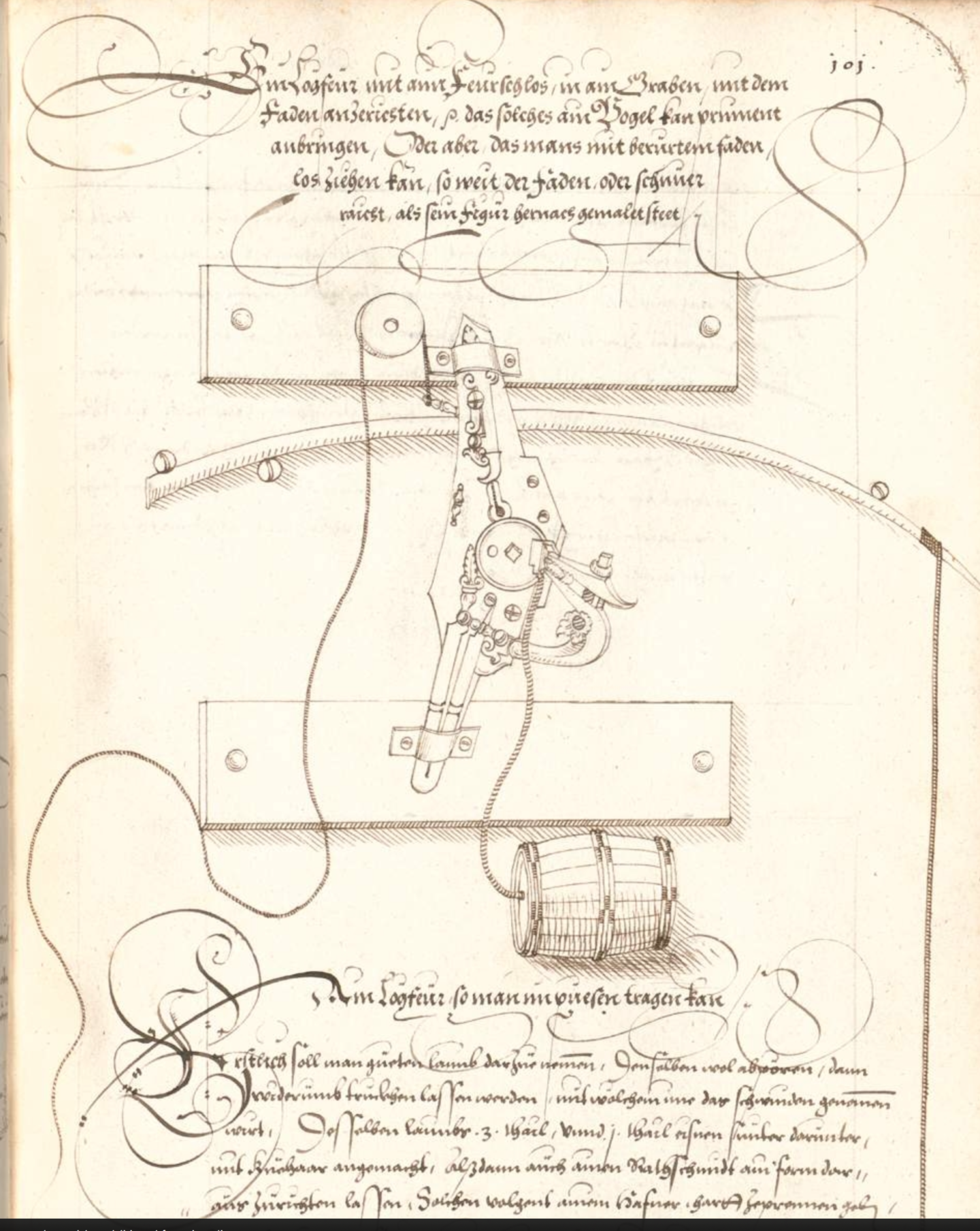
I’ve written before about a lovely diagram from the 1580s of an IED initiated by a wheel lock , with a fantastic picture I found in a book in the British Library. That post is here, but I’ll repeat this diagram below for convenience – it’s one of my favourite historical IEDs. One doesn’t need to understand the writing to work out what’s going on – note the string attached to the trigger, the wheelock mechanism and the fuze leading to a barrel of gunpowder.

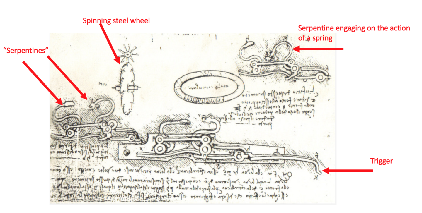
So this image was a wheel lock initiated IED from 1582, and I wanted to find an earlier example.  Some sources suggest that Leonardo Da Vinci was the “inventor”, so I’ve been hunting for Da Vinci diagrams.  Here, below, is one from the “Madrid Codex” . Whether Da Vinci actually designed this or was simply copying a design made by a German inventor is an issue for the academics. If I’m honest I can’t quite understand the diagram (and also the accompanying text!)  but I have picked out some key points.  Let me at least point these out to you:

  1. The Trigger, is at the lower right hand side.  Compare this with the trigger above at the top, tied to a piece of string which runs round a pulley.
  2. There are two Serpentines in the diagram below. A serpentine is best thought of as a lever which acts under the effect of a spring. If I’m honest I’m not certain of the purpose of the left hand one – it could be as a release-latch on the spring loaded steel spinning wheel.  The right hand serpentine I think holds the pyrites, and a spring action pushes that down when triggered. “Serpentines” were of course used before wheel locks to hold the burning fuze of a match lock, then press it into the gunpowder when a trigger was pulled releasing it. the second serpentine could though, be a failsafe, duplicate to the first.
  3. The spinning wheel is shown vertical and isolated but I suspect it was horizontal, but it’s not clear to me how this was held. I’m also not sure what the circular object in the middle is.


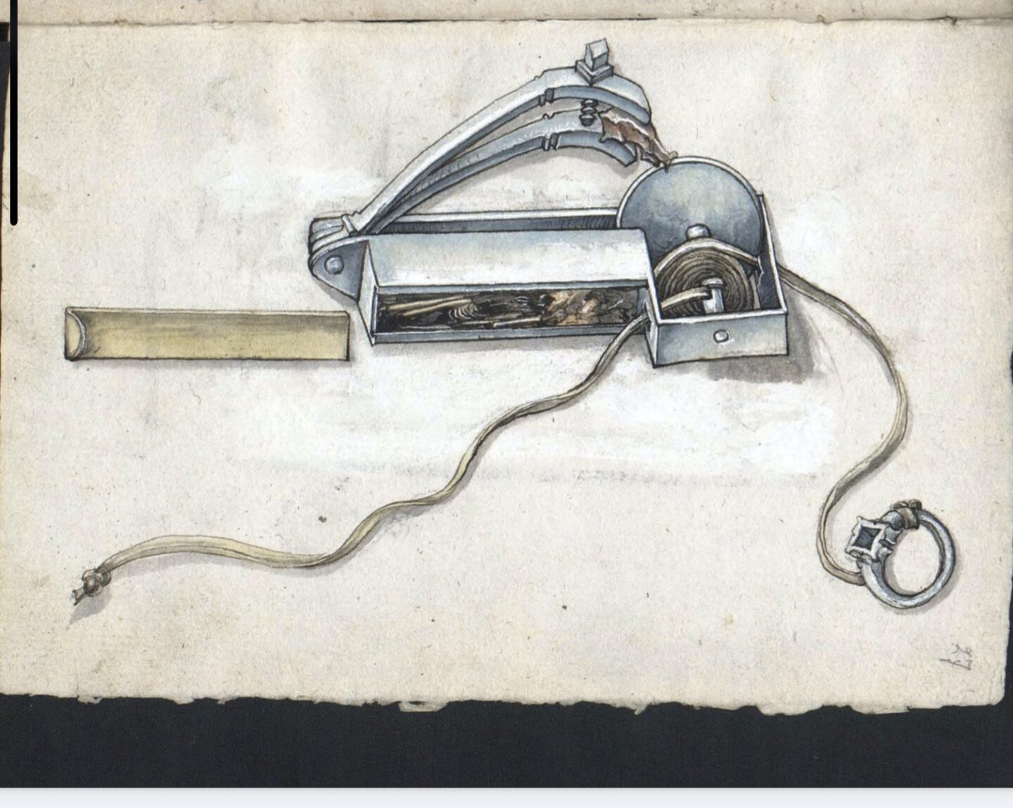
In doing some more digging I found a couple more interesting diagrams that are worth showing in the context that I think they may not be to ignite explosives, but rather to light tinder, which in effect meets the same requirement.  Perhaps these “mechanical tinder igniters” were precursors to the wheel lock. They date from the first decade of the 1500s, right in the early days of match locks and I have lifted them from the “Loffelholz Kodex”. Here’s the first:

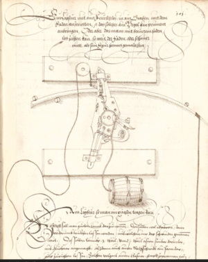
This is really a beautiful diagram, from 1505, and I think shows a pocket-sized igniter. A portable “everyday carry” from 500 years ago.  The box container contains tinder” or , if you like, gunpowder. The brass slide holds the tinder in a box. A cord is fitted to a spindle, and wound round and round. Also attached to the spindle is a steel wheel, and the serpentine holds the pyrites. The user, with a ring on his finger to which is tied the cord, pulls, the wheel spins, the pyrites is engaged , sparks fly and light the tinder. Replace the tinder with gunpowder, and run the cord as a trip wire and you have a booby trap IED.  You can see that with the addition of a clock spring ,  a release catch to allow the spring to act on the wheel and another spring to engage the pyrites, it is the same idea.

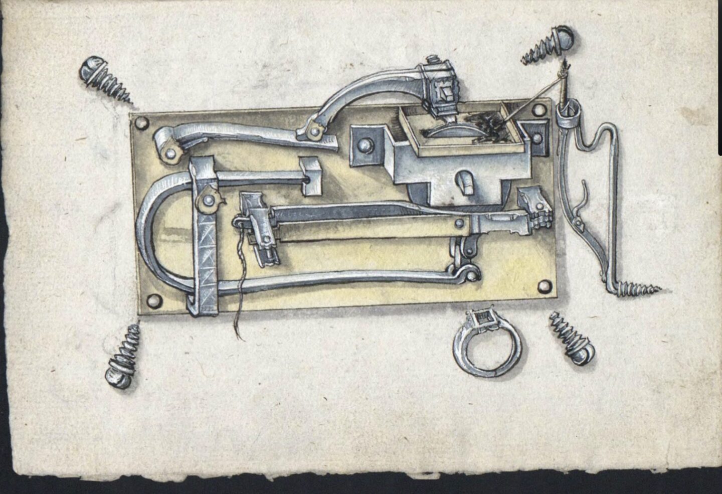
The second diagram is more complicated, and I confess I can’t quite work it out. But it is clearly a wheel lock device for some purpose or other. If you can interpret the action here, please let me know your thoughts. I can see the “wheel”, the tinder box, the serpentine holding the pyrites and one , if not two triggers, but I can’t quite work out the springs.  Clearly this is meant to be screwed onto the side of something.

What these inventions do, that previously wasn’t very easy to achieve, are:

  1. Reliable ignition of gunpowder without the need for a pre-lit burning fuze, allowing concealment in advance. This is a key IED capability. Previously any emplaced device would have been spotted by the smoke emitting from a match, and could not have been left for any length of time.
  2. Booby trap initiation – using the “string” to release a spring, or pull a spindle, both causing sparks and thence initiation of a charge.
  3. Command initiation from a distance, again using the string.
  4. Timed initiation – because a clock could be used to to cause the trigger to be pulled – and it was clock engineers who were developing the mechanisms anyway.

So these are startling new offensive capabilities for explosive devices. As such, the development of the wheel lock had perhaps more of an impact on explosive device design than on firearms. where , in battle at least, the need to conceal a burning match was not an issue.  Perhaps there was an impact though on the use of firearms in ambushes and for highway robbers, when firearms could be concealed under a cloak. Such mechanisms in firearms were quickly banned in some countries – again showing the potential for the illicit use of a mechanism such as this for nefarious effect.

As such I think that historically speaking the development of the wheel lock is one of the most significant engineering developments in the history of explosives as it provided several distance new IED capabilities.     Wheel locks were expensive to produce so the use of match locks continued for some time – flintlocks which came some time later were simpler and therefore cheaper to produce, eventually phasing out the wheel lock.  That development is in itself interesting because it was a “simpler” technology replacing a complex engineered device.

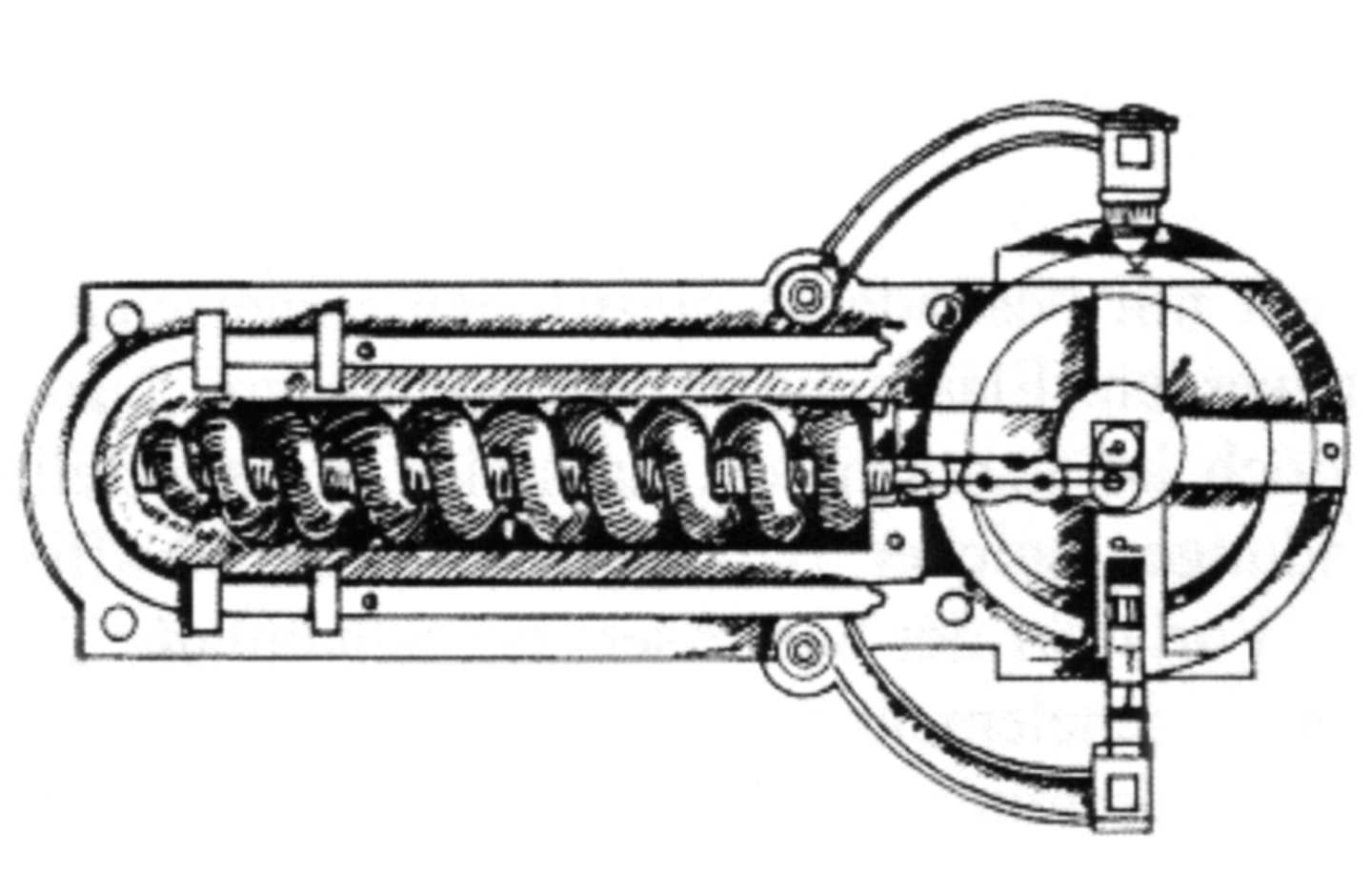
Before I finish, there’s two interesting aside. Most wheel locks used a concentric spiral spring to turn a spindle that ran through its middle. But there’s two other initiating systems , one a variant of the spring construction. This is it below, another Da Vinci Drawng, this from the Codex Alantic and you can see that the spring is a longitudinal coil rather than a spiral, but it still acts on a “wheel” that is perpendicular to the length of the spring.

Finally another approach to the same problems this not using a wheel at all but a longitudinal bar of steel pulled so that it scrapes along the pyrites. This is the Monk’s Gun, held in the Dresden Armoury. This dates from somewhere between 1480 and 1550.

Although it has no “wheel” it has the advantage (?) of being somewhat simpler. You can see the “serpentine” holing the pyrites, and the ring on the bottom is pulled to the right, causing the teeth on a steel slide to act on the pyrites producing a spark – hidden behind would have been a touch hole leading to the chamber of this simple gun.


Execution by Gunpowder

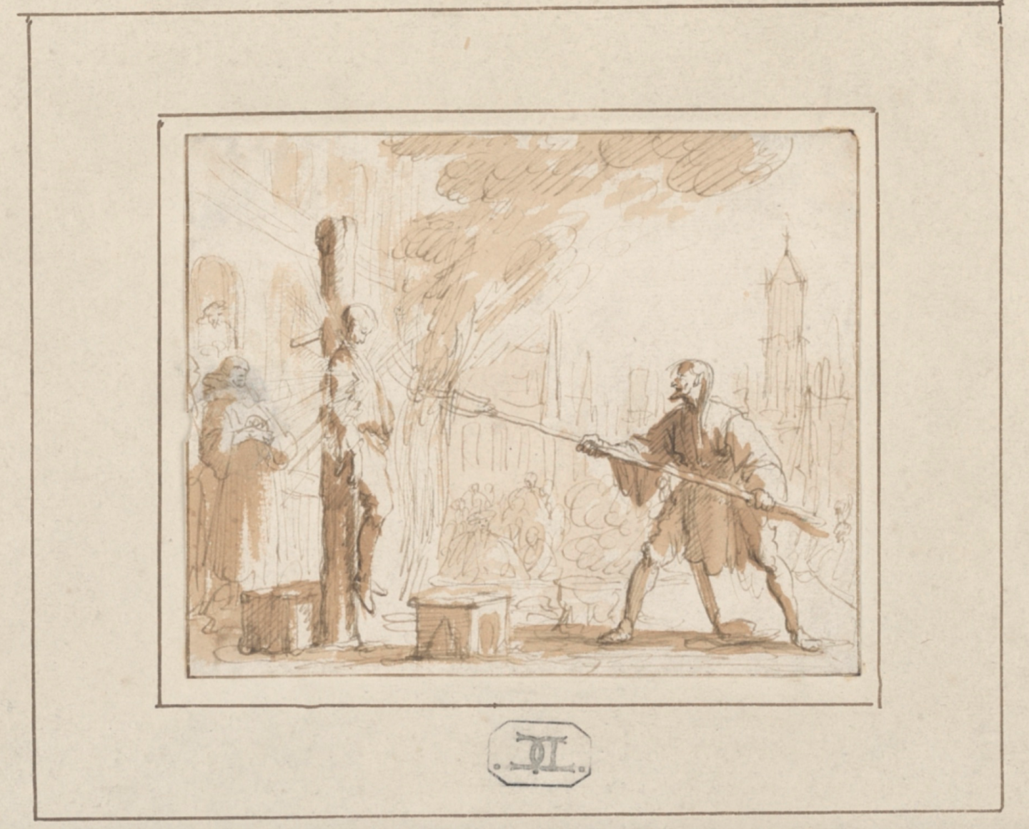
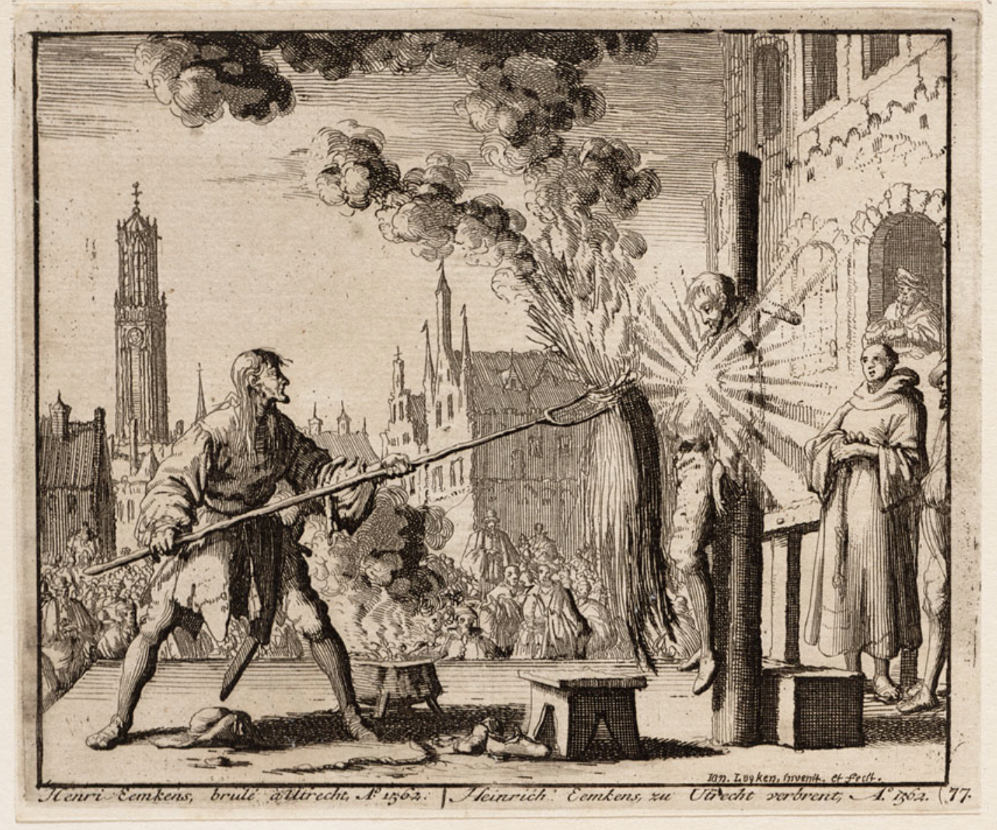
A peculiar story. In Utrecht in the Netherlands in 1562, Hendrick Eemkens was sentenced to death by a court for the crime of being an Anabaptist, a form of radical Protestantism at the time.  He was ordered to be “executed by gunpowder” in the city square in front of a crowd of people.  To achieve this he was tied to a stake and a charge of gunpowder draped around his upper body and neck. I’m not sure of the size of this charge. Some reports suggest he was throttled first.  A fire was lit close by and the executioner, using a long pitchfork, lifted a bale of burning material into contact with the explosive charge. I’ve found two images, admittedly from over a century later, showing the execution.

The second is a little more explicit

The clergy behind the victim doesn’t look like he’s standing well enough back.  One report observed that the man’s hair was not singed in the explosion.

Chinese 16th Century Ship-Borne IED

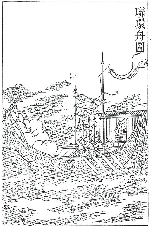
An interesting pic below.


This is from a book written in the mid-1500s by a Chinese Imperial official and shows a sophisticated vessel containing large amounts of explosives.  This and other vessels of a similar nature were made at the Dragon River Shipyard near Nanking.  There are some interesting features to this:


  1. Note the bow of the vessel – these protuberances are described as “wolf’s teeth nails”. When the vessel is rammed against the target these steel teeth engage and fasten the bow of the IED vessel to the target.
  2. Note the “hook and eye connections” amidships. This is pretty clever. After the vessel is rammed into the target the entire “bow” containing the explosives and rockets, is detached by detaching the hooks from the eyes and the attackers row away the foreshortened vessel. Other vessels from the Dragon River Shipyard utilised other designs for leaving behind explosive or combustible material and rowing a smaller boat away  – and disguise was a key design consideration.  This vessel may have looked like an ordinary commercial vessel with plenty of crew aboard and therefore not like an expected explosive ship, which were usually towed.
  3. The skipper is protected from enemy weapons in a cabin, and the rowers are equipped with long poles to defend themselves and presumably light the charge.
  4. The official describes this vessel as being 14m long, with the forward detachable section being about 1/3rd of the length, (so roughly 5m long).

Europeans (specifically the Portuguese) would have encountered these sort of attacks in their war against the Chinese in the first part of the 16th century.  So these vessels just preceded the first real European use of this sort of weapon, namely the “Hoop” at Antwerp in 1584.  In the early 17th Century the Dutch too faced such weapons in their Chinese adventures. In 1637 a small fleet of English vessels arrived in China to trade and were attacked by a small fleet of fire ships and explosive vessels.  The attack was described by a man aboard one of the ships and adventurer called “Peter Mundy”. (That name will make some of you older British EOD types smile).  Mundy writes:

“The fire was vehement. Balls of wild fire, rockets and fire arrows flew thick as they passed us, But God be praised, not one of us all was touched.”

Mundy then learned that the attack was actually inspired by the Portuguese in Macao to deter British trade competition.  This concept precedes then the development of “spar torpedoes” used frequently in the US Civil war, where an explosive charge was on the end off a spar on the front of an attacking boat, designed to attach to the target.

Command initiated explosive device from 1582

I’m steadily working my way through more military handbooks from the late 1500s when there appears to have been a lot of revolutionary thought going into military technology and explosive device development in particular. My previous post on a grenade was dated 1578, you may recall that Giambelli’s ship explosive device was 1584, and I’ve written before about a postal device in the city of Pskov in 1581.  I’ve also written before how “gun-locks” were used as initiating devices for explosives over a 250 year period.

On that latter point I’ve just found a gun lock (in this case a wheel-lock) drawn in a manuscript from Germany, dated 1582. The drawing is here and as you can see the design is very clear.


The wheel-lock was a progenitor of the flintlock which came in a few years later, in about 1600. In a wheel-lock a spring-loaded wheel spins against some pyrites held in the cock.  Here you can see how the gun lock has been removed from a firearm and fastened to a frame. A string is attached to the trigger, led around a pulley and away to the person initiating the device. When the target presents itself, the person pulls the string, which pulls the trigger. On pulling the trigger a spring mechanism spins the steel wheel against the pyrites held in the cock. This causes sparks which ignites the fuse. The fuse leads to a barrel of gunpowder hidden nearby.  In a post a few years ago I have an image showing a multiple IED attacks against a military convoy employing these exact devices, so it’s good to corroborate the attack with a contemporary IED design.

So, this is another example of how explosive device design appears to have developed rapidly at this peculiar point in history, across Europe. I think it is the publication of these handbooks and manuals of military science that seems to be helping – bu I’m afraid I’m not a good enough historian to identify other causes of this bubble of ideas. Comments from proper historians welcome!

A couple of follow-up thoughts:

1. The “pull string” could of course be adapted to a trip string, turning the command-initiated device into a victim-operated booby trap.

2. One possibility of the sudden uptick in apparent use of explosive devices at this point in history is manufacturing technology.  I wonder of clock-making saw similar technological leaps at this time.  Wheel-locks were invented in the early part of the century but are quite complex in design from an engineering and manufacturing perspective. Perhaps clock making manufacture and design took parallel leaps at this time and the transfer of ideas to wheel locks (essentially a clockwork mechanism, with a wheel powered by a spring) enabled cheaper device components and they became more commonly available rather than the early wheel locks which were the weapons of the rich.  I’ve just read that coiled carbon steel spring (essential for wheel locks) was first made possible in the early 1500s – perhaps manufacture became easier in the 1570s, allowing them to be more easily and cheaply manufactured, and hence available for regular soldier’s weapons and “one-time use” in explosive devices. Perhaps the wheel lock mechanisms, like in the diagram above, were separated from the main charge and were thus in theory recoverable after the event.

Close Me
Looking for Something?
Search:
Post Categories: